Xen Networking
Contents
Virtual Network Interfaces
Paravirtualised Network Devices
A Xen guest typically has access to one or more paravirtualised (PV) network interfaces. These PV interfaces enable fast and efficient network communications for domains without the overhead of emulating a real network device. Drivers for PV network devices are available by default in most PV aware guest OS kernels. In addition PV network drivers are available for various guest operating systems when running as a fully virtualised (HVM) guest, e.g. via PV on HVM drivers for Linux or the GPL PV drivers for Windows.
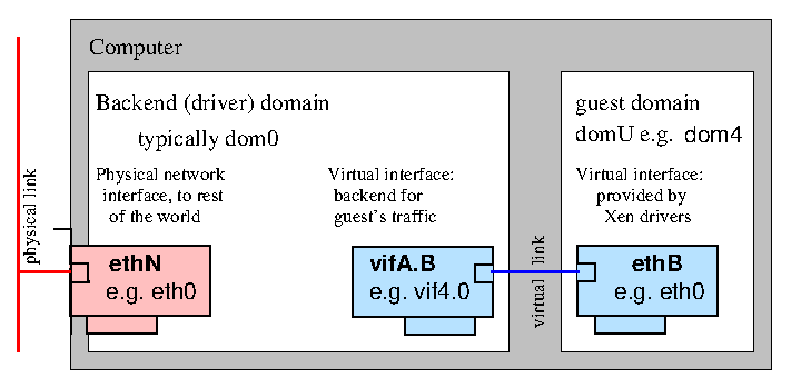
A paravirtualised network device consists of a pair of network devices. The first of these (the frontend) will reside in the guest domain while the second (the backend) will reside in the backend domain (typically Dom0). A similar pair of devices is created for each virtual network interface
The frontend devices appear much like any other physical Ethernet NIC in the guest domain. Typically under Linux it is bound to the xen-netfront driver and creates a device ethN. Under NetBSD and FreeBSD the frontend devices are named xennetN and xnN respectively.
The backend device is typically named such that it contains both the guest domain ID and the index of the device. Under Linux such devices are by default named vifDOMID.DEVID while under NetBSD xvifDOMID.DEVID is used.
In both cases the device naming is subject to the usual guest or backend domain facilities for renaming network devices. For the remainder of this document the default Linux naming, that is ethN for frontend and vifDOMID.DEVID for backend devices, will be used.
The front and backend devices are linked by a virtual communication channel, guest networking is achieved by arranging for traffic to pass from the backend device onto the wider network, e.g. using bridging, routing or Network Address Translation (NAT).
Emulated Network Devices
As well as PV network interface fully virtualised (HVM) guests can also be configured with one or more emulated network devices. These devices emulate a real piece of hardware and are useful when a guest OS does not have PV drivers available or when they are not yet available (i.e. during guest installation).
An emulated network device is usually paired with a PV device with the same MAC address and configuration. This allows the guest to smoothly transition from the emulated device to the PV device when a driver becomes available.
The emulated network device is provided by the device model, running either as a process in domain 0 or as a Stub Domain.
When the DM runs as a process in domain 0 then the device is surfaced in the backend domain as a tap type network device. Historically these were named either tapID (for an arbitrary ID) or tapDOMID.DEVID. More recently they have been named vifDOMID.DOMID-emu to highlight the relationship between the paired PV and emulated devices.
If the DM runs in a stub domain then the device surfaces in domain 0 as a PV network device attached to the stub domain. The stub domain will take care of forwarding between the device emulator and this PV device.
For the remainder of this document PV and Emulated devices are mostly interchangeable and we will use the PV naming in the examples.
MAC addresses
Virtualised network interfaces in domains are given Ethernet MAC addresses. By default most Xen toolstacks will select a random address, depending on the toolstack this will either be static for the entire life time of the guest (e.g. Libvirt, XAPI or xend managed domains) or will change each time the guest is started (e.g. XL or xend unmanaged domains).
In the latter case if a fixed MAC address is required e.g. for using with DHCP then this can be be configured using the mac= option to the vif configuration directive (e.g. vif = ['mac=aa:00:00:00:00:11']). See XL Network Configuration for more details of the syntax.
When choosing MAC addresses there are in general three strategies which can be used. In decreasing order of preference these are:
- Assign an address from the range associated with an Organizationally Unique Identifier (OUI) which you control. If you do not know what this means then you likely do not control an OUI and this option does not apply to you.
- Generate a random sequence of 6 bytes, set the locally administered bit (bit 2 of the first byte) and clear the multicast bit (bit 1 of the first byte). In other words the first byte should have the bit pattern xxxxxx10 (where x is a randomly generated bit) and the remaining 5 bytes are randomly generated. See wikipedia for more details the structure of a MAC address.
- Assign a random address from within the space 00:16:3e:xx:xx:xx. 00:16:3e is an OUI assigned to the Xen project and which has been made available for Xen users for the purposes of assigning local addresses within that space.
A MAC address must be unique among all network devices (both physical and virtual) on the same local network segment (e.g. on the LAN containing the Xen host). For this reason if you do not have your own OUI to use it is in general recommended to generate a random locally administered address (the second option above) rather than using the Xen OUI (the third option) since it gives 46 bits of randomness rather than 24 which significantly reduces the chances of a clash.
Bridging
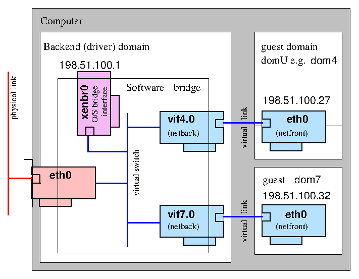
The default (and most common) Xen configuration uses bridging within the backend domain (typically domain 0) to allow all domains to appear on the network as individual hosts.
In this configuration a software bridge is created in the backend domain. The backend virtual network devices (vifDOMID.DEVID)) are added to this bridge along with an (optional) physical Ethernet device to provide connectivity off the host. By omitting the physical Ethernet device an isolated network containing only guest domains can be created.
There are two common naming schemes when using bridged networking. In one scheme the physical device eth0 is renamed to peth0 and a bridge named eth0 is created. In the other the physical device remains eth0 while the bridge is named xenbr0 (or br0 etc). We shall use the eth0+xenbr0 naming scheme here.
Of course you are free to use whatever names you like, including descriptive names (e.g. "dmz", "internal", "external" etc).
Setting up bridged networking
The recommended method for configuring bridged networking is to use your distro supplied network configuration tools as described in Host Configuration/Networking.
Prior to Xen 4.1 when xend started up it would run the network-bridge script which would reconfigure any existing physical network configuration into a bridged network configuration i.e. it would create a bridge, move the IP address from the physical device to the bridge, add the physical device to the bridge etc. However this was fragile and prone to breaking and therefore is no longer recommended.
After Xen 4.1 xend will only do this if no bridges currently exist, so as to avoid overwriting any locally configured network configuration.
The XL toolstack will never modify the network configuration and expects that the administrator will have configured the host networking appropriately. Check out this XL example.
Attaching virtual devices to the appropriate bridge
When a domU starts up the vif-bridge script is run which:
- attaches vifDOMID.DEVID to the appropriate bridge
- brings vifDOMID.DEVID up.
With XL and xend the bridge to use for each VIF can be configured using the bridge configuration key. e.g.
vif=[ 'bridge=mybridge' ]
or
vif=[ 'mac=00:16:3e:01:01:01,bridge=mybridge' ]
or to create multiple interfaces attached to different bridges:
vif=[ 'mac=00:16:3e:70:01:01,bridge=br0', 'mac=00:16:3e:70:02:01,bridge=br1' ]
Bridging Loops
It is common practice to disable the Spanning Tree Protocol on Xen bridges. However if guests are able to themselves bridge two or more interfaces together then you run the risk of creating bridging loops. See Xen Bridge Loop for more discussion of this issue.
Links
Some relevant topics from the mailing list:
Many of the links presented here are rather old and may refer to configurations which are no longer best practice, such as the use of the network-* scripts to configure networking.
|
- eth0 IP in dom0 2005/01/14
- Bridging vs. Routing 2005/01/13
- Bridging vs. Routing 2004/07/18
- An attempt to explain Xen networking 2006-02-01
- Firewall in domU with bridging
- Xen and the Art of Consolidation (with bridging)
- Another way for making multiple Xen bridges
- Advanced bridging (2007/05)
- Creating additional Xen virtual network bridges
Open vSwitch
The Xen 4.3 release will feature initial integration of Open vSwitch based networking. Conceptually this is similar to a bridged configuration but rather than placing each vif on a Linux bridge instead an Open vSwitch switch is used. Open vSwitch supports more advance Software-defined Networking (SDN) features such as OpenFlow.
Setting up Open vSwitch networking
Set up openvswitch according to the Host Networking Configuration Examples.
If you want openvswitch to be the default, add the following line to your xl.conf file:
vif.default.script="vif-openvswitch"
If you have given the openvswitch bridge a name other than xenbr0, you will need to update that default as well:
vif.default.bridge="ovsbr0"
Alternately, you can specify the new script (and bridge, if necessary) in each config file by adding script=vif-openvswitch (and possibly bridge=ovsbr0) to the vifspec of individual vifs in config files. See xl-network-configuration.markdown for more information.
vif = [ 'script=vif-openvswitch,bridge=ovsbr0' ]
Attaching virtual devices to the appropriate switch
Xen 4.3 ships with a vif-openvswitch hotplug script which behaves similarly to the vif-bridge script, except that it attaches the VIF to an openvswitch switch (named via the VIF's bridge parameter).
In addition to naming the bridge the openvswitch hotplug script supports an extended syntax for the bridge optio which allows for VLAN tagging and trunking. That syntax is:
BRIDGE_NAME[.VLAN][:TRUNK:TRUNK]
To add a vif to VLAN 102 on bridge xenbr0:
vif = [ 'mac=00:16:3e:01:01:01,bridge=xenbr0.102' ]
To add a vif to bridge xenbr1 trunked and receiving traffic for VLAN 101 and 202:
vif = [ 'mac=00:16:3e:01:01:01,bridge=xenbr1:101:202' ]
Routing
In a routed network configuration a point-to-point link is created between the backend domain (typically domain 0) and each domU virtual network interface. Traffic is then routed between these point-to-point links and the outside world using the backend domain's network routing functionality.
For a general discussion of network routing see the wikipedia page on the subject.
Because routes are created dynamically as domains are created it is usually necessary for each guest network interface to have a known static IP address.
Setting up routing on the host
The recommended method for configuring networking is to use your distro supplied network configuration tools as described in Host Configuration/Networking.
Prior to Xen 4.1 when xend started up it would run the network-route script which perform the necessary configuration. However this mechanism was fragile and prone to breaking and therefore is no longer recommended.
The XL toolstack will never modify the network configuration and expects that the administrator will have configured the host networking appropriately. Check out this XL example.
Associating routes with virtual devices
When domU starts up, the vif-route script is run for each virtual device vifDOMID.DEVID. This script sets up routing for that device by
- Adding an IP address to the device. This address is largely arbitrary but required in order that the interface can be involved in routing. By default domain 0's IP address is used.
- Brings up the device.
- Adds a host static route for the interfaces IP address as specified in domU config file routing traffic to the vifDOMID.DEVID interface.
The IP address associated with a virtual network interface should be specified in the domain configuration file using the ip configuration key.
vif=[ 'ip=192.168.1.12' ]
or
vif=[ 'mac=00:16:3e:01:01:01,ip=192.168.1.12' ]
or for multiple devices:
vif=[ 'mac=00:16:3e:70:01:01,ip=192.168.13.15', 'mac=00:16:3e:70:02:01,ip=192.168.75.11' ]
More information on vif-route can be found here.
Network Address Translation
Network Address Translation or NAT is a form of routing which gives each guest VIF its own IP address on a private/internal network, often using RFC1918 addresses, and performs address translation at the router/firewall (e.g. domain 0) to connect the entire private network to the rest of the network via a single public IP address.
NAT is sometimes also called "IP masquerading".
Setting up NAT on the host
Setting up NAT is similar to configuring Routing as described above with the most obvious difference being that one should enable NAT in the backend domain.
The recommended method for configuring networking is to use your distro supplied network configuration tools as described in Host Configuration/Networking.
Prior to Xen 4.1 when xend started up it would run the network-nat script which perform the necessary configuration. However this mechanism was fragile and prone to breaking and therefore is no longer recommended.
The XL toolstack will never modify the network configuration and expects that the administrator will have configured the host networking appropriately. Check out this XL example.
Virtual Device Configuration
In a NAT'd configuration virtual devices are given IP addresses on a private network, typically an RFC1918 internal network. Guests may either be configured statically with addresses in the chosen network space or you can chose to run a DHCP server within that network (perhaps on the host itself) to provide addresses to guests.
When domU starts up, the vif-nat script is run for each virtual device vifDOMID.DEVID. If the ISC DHCP server is install then this script will attempt to dynamically reconfigure the DHCP service to serve up entries for the mac and ip address configuration keys in the guest configuration file. This is specific to the ISC DHCP servers configuration file syntax so if you are using a different DHCP server or simply want to manage the DHCP server yourself then you should disable the vif-nat script (which seems like a good idea, since automatic editing of the DHCP configuration is bound to be fragile).
VLANs & Bonding
Multiple tagged VLANs can be supported by configuring 802.1Q VLAN support into the backend domain (typically domain 0).
Once configured according to Host Configuration/Networking then the VLAN devices can be treated like any other device and used for either routing or bridging.
Likewise bonding (or even VLANs over bonding etc) can also be created by following distribution specific documentation and treating the resulting device as normal.
Advanced configurations
By combining the above with the networking capabilities of the host OS it is possible to create more complex configurations to suit various different requirements.
- Virtual network using a brouter.
- This configuration uses a bridge with no physical device shared by the guests. The bridge an IP address in domain 0 which is then use routed (or even NATed) to the external network (hence bridged router). See "Xen3 and a Virtual Network" for a more complete description of this type of configuration.
ASCII Art Examples of Xen Networking Topologies
The following attempt to show some common networking topologies used with Xen. See Network Configuration Examples (Xen 4.1+) for examples of how to achieve these configurations using distribution provided tools.
Standard Bridged Networking Architecture
      LAN0                                                  LAN1
       |                                                     |
 +-----+-----------------------------------------------------+-----+
 |     |                                                     |     |
 | +---+-------------------------+ +-------------------------+---+ |
 | |   |                         | |                         |   | |
 | | eth0                        | |                        eth1 | |
 | |                             | |                             | |
 | | xenbr0       vif1.0  vif2.0 | |  vif1.1  vif2.1      xenbr1 | |
 | |                |       \    | |    /       |                | |
 | +---^------------+---------\--+ +--/---------+------------^---+ |
 |     |            |           \   /           |            |     |
 |     |     +------+-------------X-------------+------+     |     |
 |     |     |      |           /   \           |      |     |     |
 |     |     | +----+---------/--+ +--\---------+----+ |     |     |
 |     |     | |    |       /    | |    \       |    | |     |     |
 |     |     | |  eth0    eth1   | |   eth0   eth1   | |     |     |
 |     |     | |    |       |    | |    |       |    | |     |     |
 |   +-+-+   | |  +-+-+   +-+-+  | |  +-+-+   +-+-+  | |   +-+-+   |
 |   |   |   | |  |   |   |   |  | |  |   |   |   |  | |   |   |   |
 |  www ssh  | | www ssh ftp pop | | www ssh ftp pop | |  ftp pop  |
 |           | |                 | |                 | |           |
 |  Domain0  | |     Domain1     | |     Domain2     | |  Domain0  |
 +-----------+ +-----------------+ +-----------------+ +-----------+
Notes:
- xenbrX has an active address, which is used by dom0 to communicate with outside.
Xen Networking with VLANs
      LAN0                                                  LAN1
       |                                                     |
 +-----+-----------------------------------------------------+-----+
 |     |                                                     |     |
 |   eth0                                                  eth1    |
 |     |                                                     |     |
 | +---+-------------------------+ +-------------------------+---+ |
 | |   |                         | |                         |   | |
 | | eth0.100                    | |                    eth1.200 | |
 | |                             | |                             | |
 | | xenbr0       vif1.0  vif2.0 | |  vif1.1  vif2.1      xenbr1 | |
 | |                |       \    | |    /       |                | |
 | +---^------------+---------\--+ +--/---------+------------^---+ |
 |     |            |           \   /           |            |     |
 |     |     +------+-------------X-------------+------+     |     |
 |     |     |      |           /   \           |      |     |     |
 |     |     | +----+---------/--+ +--\---------+----+ |     |     |
 |     |     | |    |       /    | |    \       |    | |     |     |
 |     |     | |  eth0    eth1   | |   eth0   eth1   | |     |     |
 |     |     | |    |       |    | |    |       |    | |     |     |
 |   +-+-+   | |  +-+-+   +-+-+  | |  +-+-+   +-+-+  | |   +-+-+   |
 |   |   |   | |  |   |   |   |  | |  |   |   |   |  | |   |   |   |
 |  www ssh  | | www ssh ftp pop | | www ssh ftp pop | |  ftp pop  |
 |           | |                 | |                 | |           |
 |  Domain0  | |     Domain1     | |     Domain2     | |  Domain0  |
 +-----------+ +-----------------+ +-----------------+ +-----------+
Notes:
- With this configuration, DomUs are completely unaware of the fact that they are utilizing a VLAN, all the work is done within the bridges in Dom0.
- Dom0 is aware of the traffic within the VLAN, because it has an active address on the xenbrX interfaces. To prevent it, don't give the xenbrX an active address, but configure a extra interface for management.
- There are two things may need to be configured:
- If your ethernet card does not natively support VLAN tags, you will have to set the maximum MTU to 1496 to make room for the tag. With command:
# ifconfig eth0 mtu 1496
- With the DomUs bridged to VLAN interfaces, some optimizations need to be disabled or tcp and udp connections will fail. This is done by disabling transmit checksum offloading:
# ethtool -K eth0 tx off
Xen Networking with bonding
              PRT0 PRT1                       PRT2 PRT3
                |   |                           |   |
 +--------------+---+---------------------------+---+--------------+
 |              |   |                           |   |              |
 |            eth0 eth1                       eth2 eth3            |
 |              |   |                           |   |              |
 |              +-+-+                           +-+-+              |
 |                |                               |                |
 | +--------------+--------------+ +--------------+--------------+ |
 | |              |              | |              |              | |
 | |            bond0            | |            bond1            | |
 | |                             | |                             | |
 | | xenbr0       vif1.0  vif2.0 | |  vif1.1  vif2.1      xenbr1 | |
 | |                |       \    | |    /       |                | |
 | +---^------------+---------\--+ +--/---------+------------^---+ |
 |     |            |           \   /           |            |     |
 |     |     +------+-------------X-------------+------+     |     |
 |     |     |      |           /   \           |      |     |     |
 |     |     | +----+---------/--+ +--\---------+----+ |     |     |
 |     |     | |    |       /    | |    \       |    | |     |     |
 |     |     | |  eth0    eth1   | |   eth0   eth1   | |     |     |
 |     |     | |    |       |    | |    |       |    | |     |     |
 |   +-+-+   | |  +-+-+   +-+-+  | |  +-+-+   +-+-+  | |   +-+-+   |
 |   |   |   | |  |   |   |   |  | |  |   |   |   |  | |   |   |   |
 |  www ssh  | | www ssh ftp pop | | www ssh ftp pop | |  ftp pop  |
 |           | |                 | |                 | |           |
 |  Domain0  | |     Domain1     | |     Domain2     | |  Domain0  |
 +-----------+ +-----------------+ +-----------------+ +-----------+
Xen Networking with vlan on bonding
              PRT0 PRT1                       PRT2 PRT3
                |   |                           |   |
 +--------------+---+---------------------------+---+--------------+
 |              |   |                           |   |              |
 |            eth0 eth1                       eth2 eth3            |
 |              |   |                           |   |              |
 |              +-+-+                           +-+-+              |
 |                |                               |                |
 |              bond0                           bond1              |
 |                |                               |                |
 | +--------------+--------------+ +--------------+--------------+ |
 | |              |              | |              |              | |
 | |          bond0.100          | |          bond1.200          | |
 | |                             | |                             | |
 | | xenbr0       vif1.0  vif2.0 | |  vif1.1  vif2.1      xenbr1 | |
 | |                |       \    | |   	/       |                | |
 | +---^------------+---------\--+ +--/---------+------------^---+ |
 |     |            |           \   /           |            |     |
 |     |     +------+-------------X-------------+------+     |     |
 |     |     |      |           /   \           |      |     |     |
 |     |     | +----+---------/--+ +--\---------+----+ |     |     |
 |     |     | |    |       /    | |    \       |    | |     |     |
 |     |     | |  eth0    eth1   | |   eth0   eth1   | |     |     |
 |     |     | |    |       |    | |    |       |    | |     |     |
 |   +-+-+   | |  +-+-+   +-+-+  | |  +-+-+   +-+-+  | |   +-+-+   |
 |   |   |   | |  |   |   |   |  | |  |   |   |   |  | |   |   |   |
 |  www ftp  | | www ftp ssh dns | | www ftp ssh dns | |  ssh dns  |
 |           | |                 | |                 | |           |
 |  Domain0  | |     Domain1     | |     Domain2     | |  Domain0  |
 +-----------+ +-----------------+ +-----------------+ +-----------+
Notes:
- The connections at the top are switch ports - probably on 2 switches with an ISL
- bond0 has eth0 and eth1 ; bond1 has eth2 and eth3
- In the VMs eth0 maps to bond0.100 and eth1 maps to bond1.200
- Protocols suggest a service VLAN (100) and a mgmt VLAN (200)